Documentation
3934 Electric Motor Certification
MS-3934: Vibration Analysis Studio iPadOS® version
- Version: 1.49 (b.126)
- Author: D. Bukowitz
- Created: 31 Mar, 2021
- Update: 21 Nov, 2022
If you have any questions that are beyond the scope of this document, Please feel free to email via info@sens-os.com
Description
This module is designed to perform a vibration acceptance test on an electric-motor using 2 triaxial points (6 readings) using the traditional industrial vibration standards. It will also provide a response message if a fault is detected in the motor.
Compatibility
This module is compatible with the following sensors:
- SensorWorks BluVib P-V-T (1 Axis)
- SensorWorks BluVib M-V-T-3 (3 Axis)
- EI-WiSER™3X (3 Axis)
- Sensoteq® Chi (3 Axis)
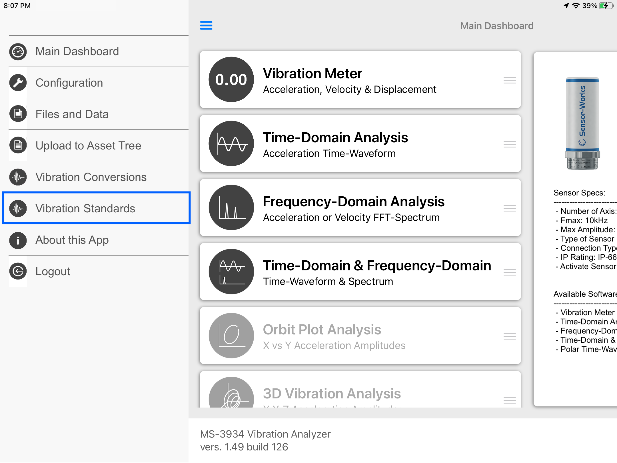
Main Menu
- Tap on the Sensor name button to open the list of available sensors, and select the sensor type from the list
- Scroll the list of functionalities and select Electric Motor Certification.
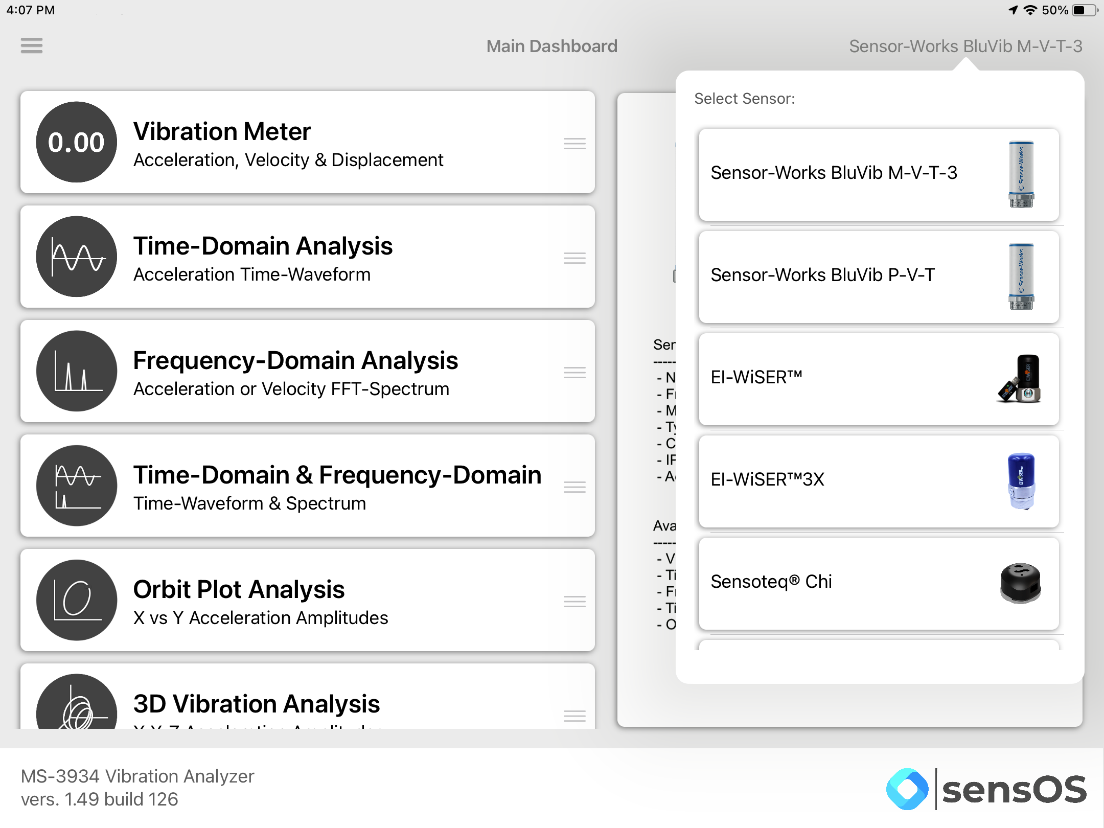
Note: The user can change the order of the functionalities in the list by dragging it from the right button on each cell
Electric Motor Certification
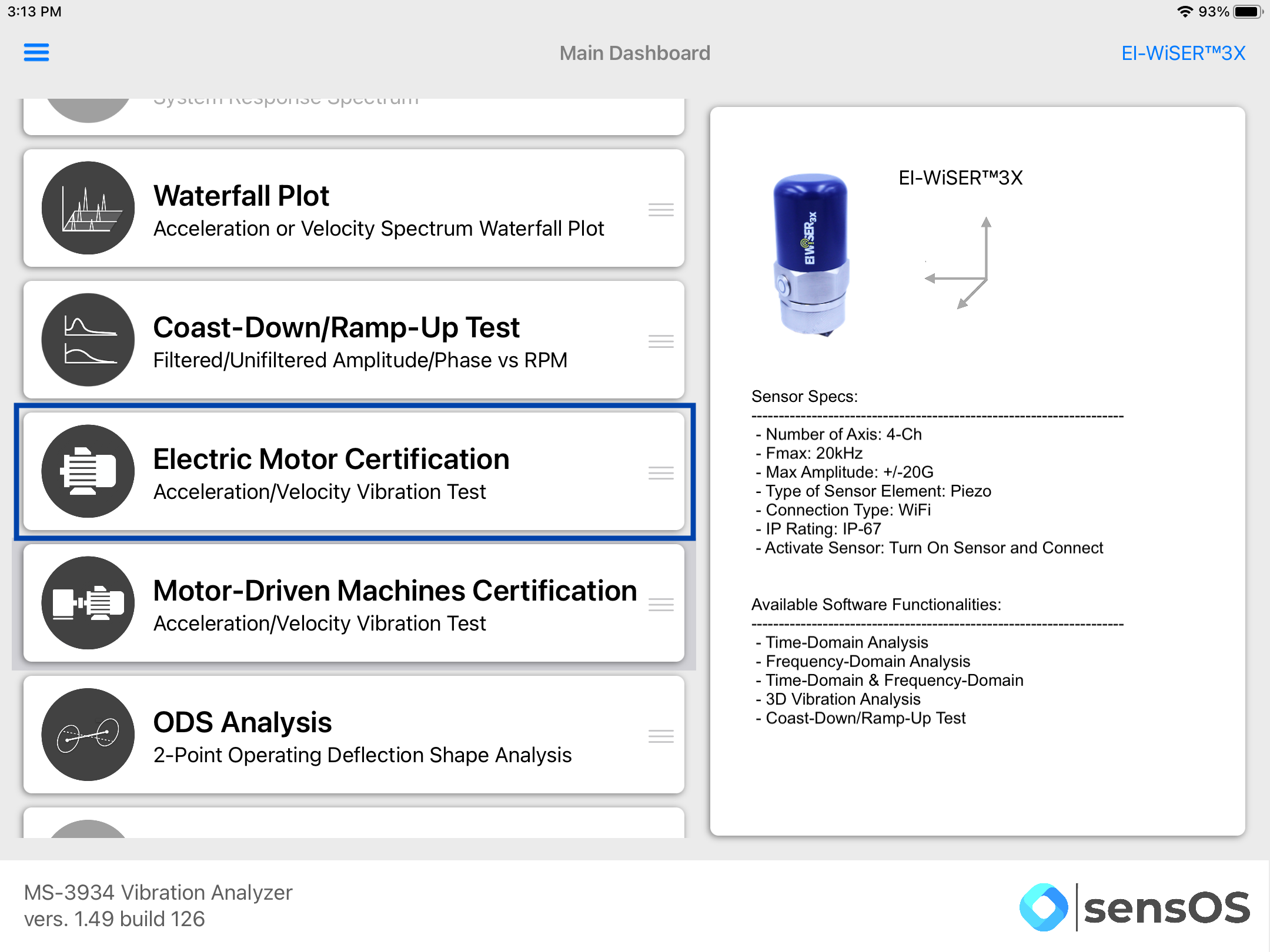
- Select the machine type from the list, as shown below.
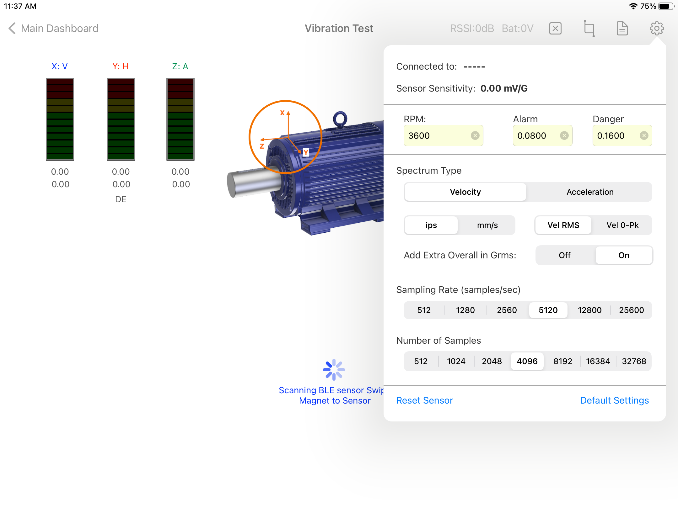
- In the settings pop-up set the sampling rate, number of samples, spectrum type and units. Also, set the vibration's threshold, user can set manual values for the thresholds or can use the vibration standards calculator included in the main menu left drawer, for more information refer to the Vibraton Standards feature in this document. Other settings changes such as cut-off value, filters and windowing can be changes in the Main Configuration, see Configuration for more details
- For the EI-WiSer3X turn On the sensor and click 'Tap to Connect' on the top bar. For BluVib sensors swipe a magnet to the sensor and a list of the available sensors will appear, select one. For the Sensoteq Chi a list of the available sensors will appear, select one to connect.
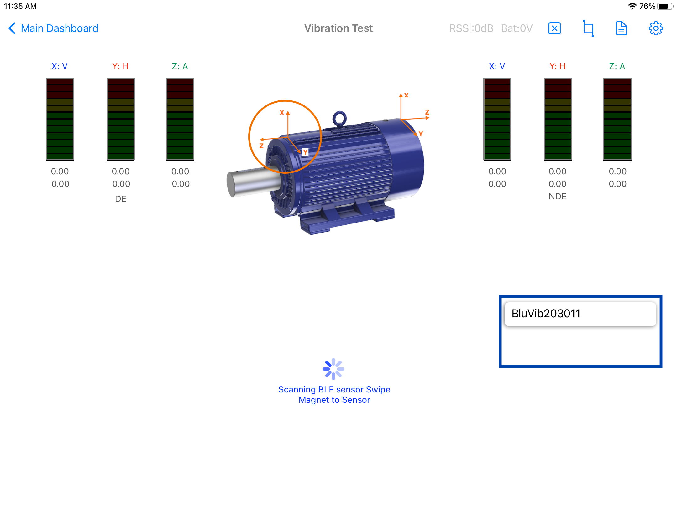
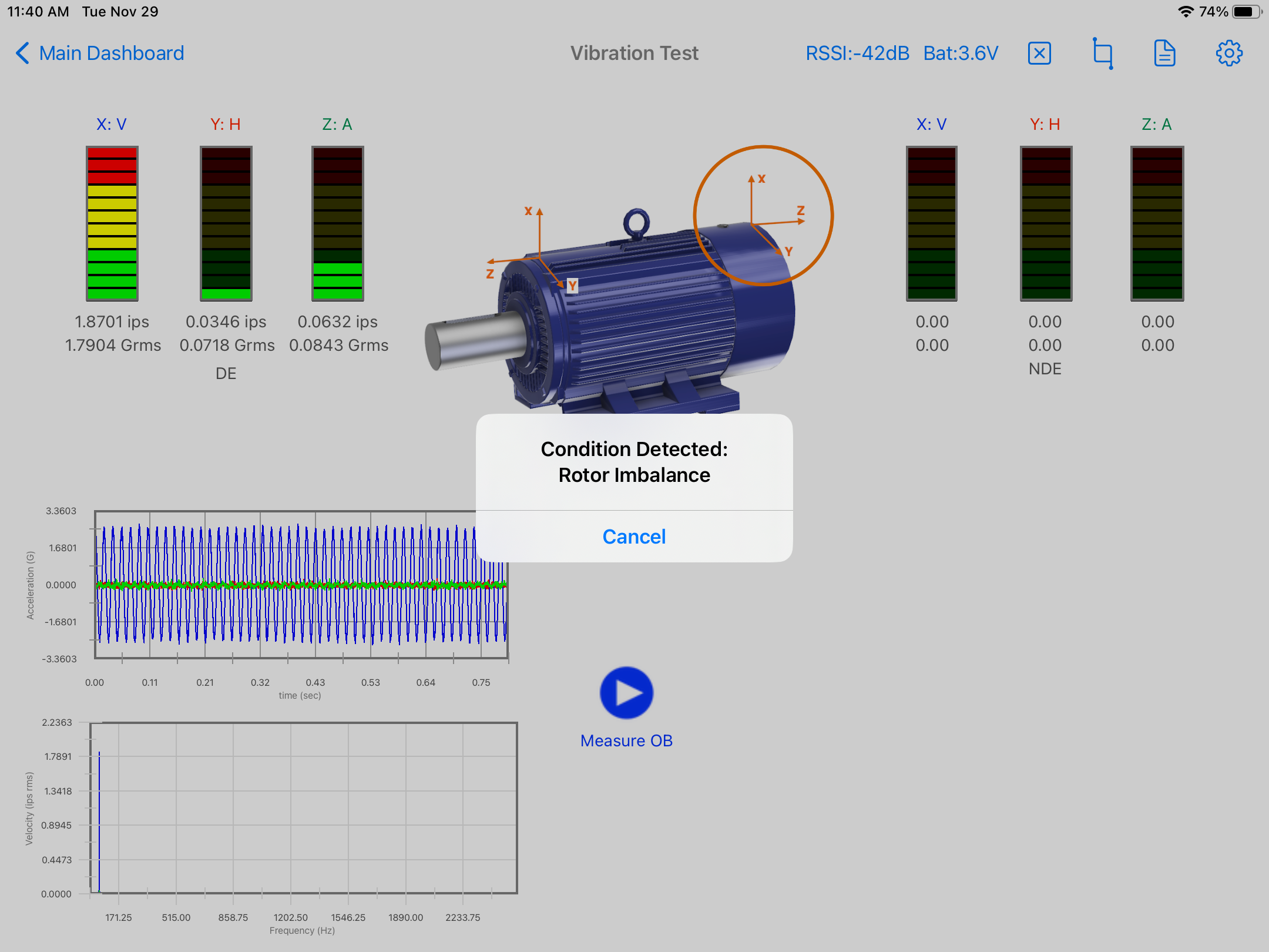
- Once the sensor is connected the start button '▶︎' will be enabled. Place the sensor in the position shown by the circle and click on the start button '▶︎'. After the reading is done the circle will move automatically to the next point, the user can delete the reading by pressing the [X] button in the top menu bar. Once a reading is taken, if the system detects a fault for the triaxial point, a pop-up dialog box will appear with the condition, as shown below.
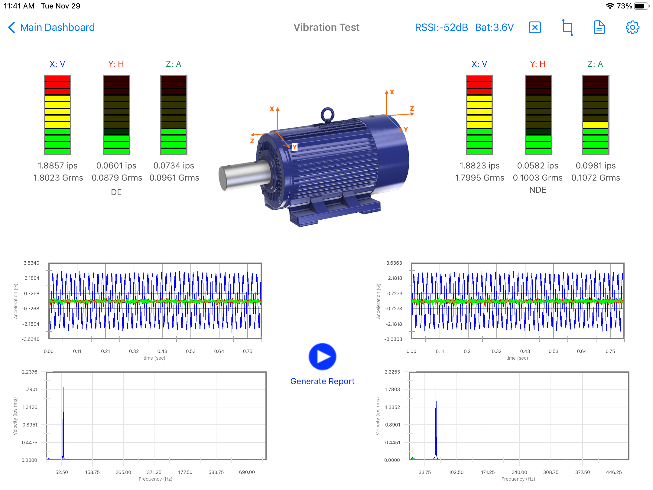
- The circle now will move to the next point, click on the start button '▶︎' again to take the second reading.
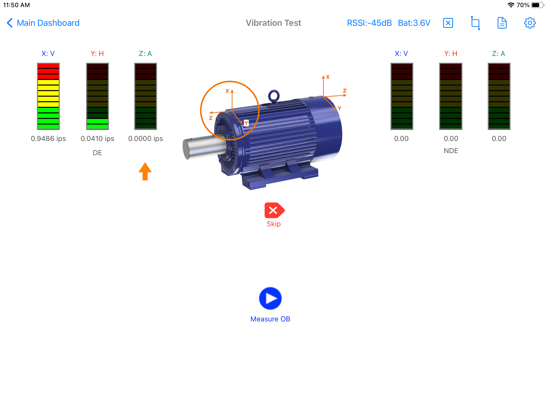
- In the case of a single-axis sensor, i.e. BluVib P-V-T the cricle will show the actual point of the reading and an arrow will show the axis to be measured. Move the sensor to each position/axis and click Start '▶︎' for each reading. Any axis reading can be skipped by pressing the 'Skip' button.
- A full pdf report can be generated, saved or sent by clicking on the report button, see more info in: Generating a pdf Report.

Note: When using ISO Standard for vibration velocity, set the sampling rate to 25,600Hz (fmax:10,000Hz) and a minimum number of samples of 8,192.
Configuration
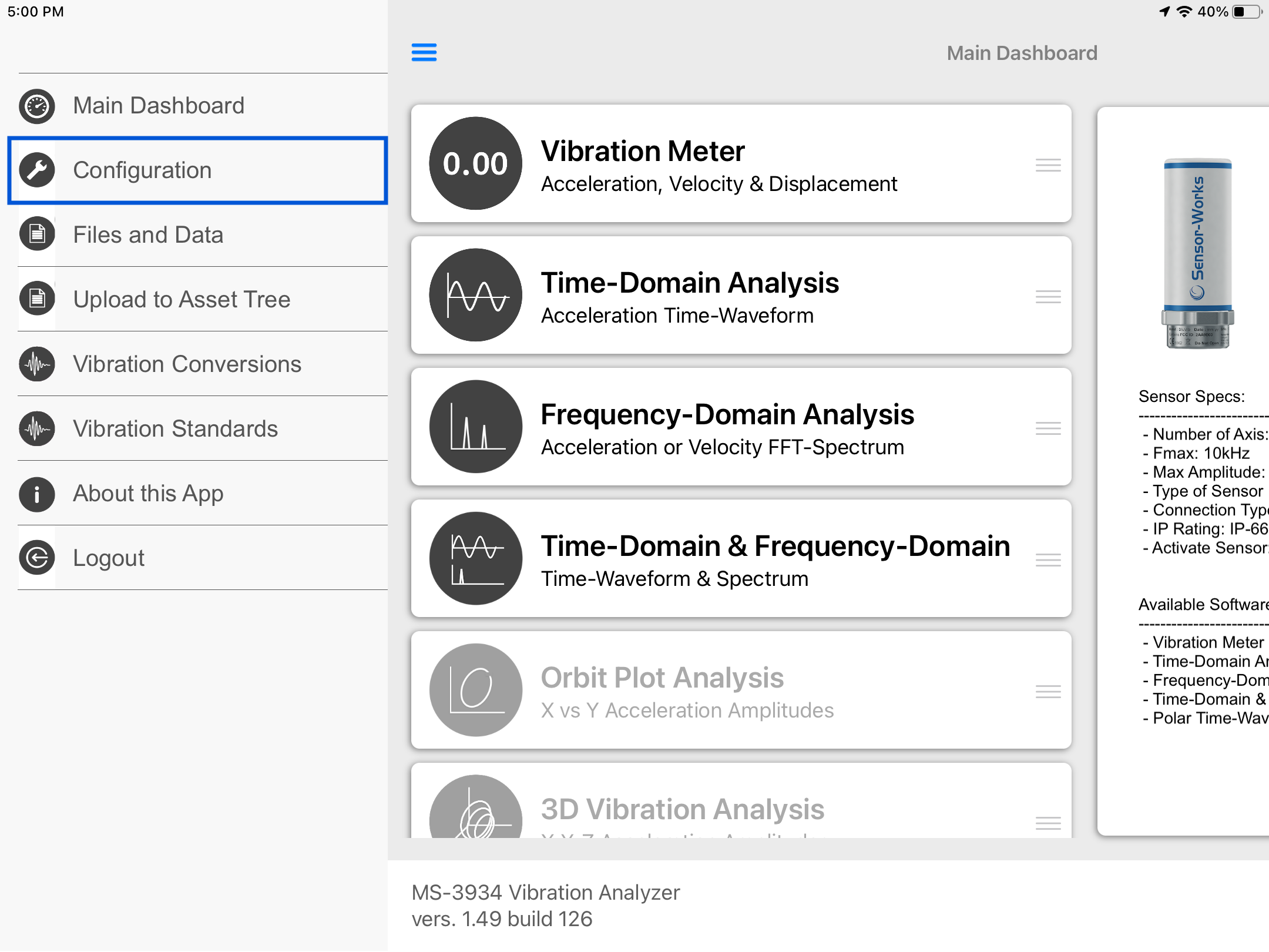
- From the Main menu, click the top left menu button to open the left drawer with more options. Select 'Configuration' from the left menu
- Select the Plot Thickness, Cursor Thickness and/or Cursor Line Type from the Plot Settings selectors.
- The Signal Settings will affect the raw data directly. The DC-Removal is ON by default by can be turned OFF here. Also a general Low-Pass or High_pass filter can be applied to the signal.
- The FFT Settings will be set as defaults for all readings. Here the user can change the spectrum frequency units to Hz, CPM or Orders. A Cut-Off value can be added to remove low frequency values. Also windowing can be selected for the spectrum, the available options are: None, Hanning, Hamming, Blackman, Nutall and Flat-Top. The spectrum type and RMS/Pk values can be set as defaults here, but can also be changed in the settings pop-up of the spectrum.
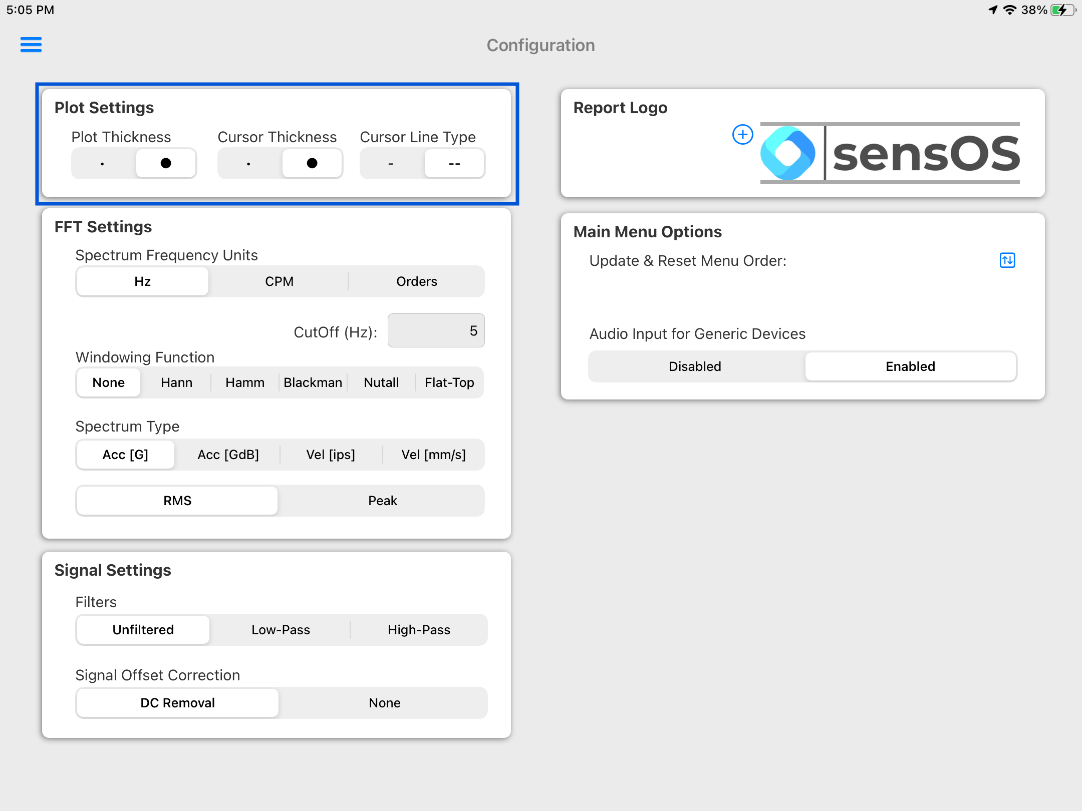
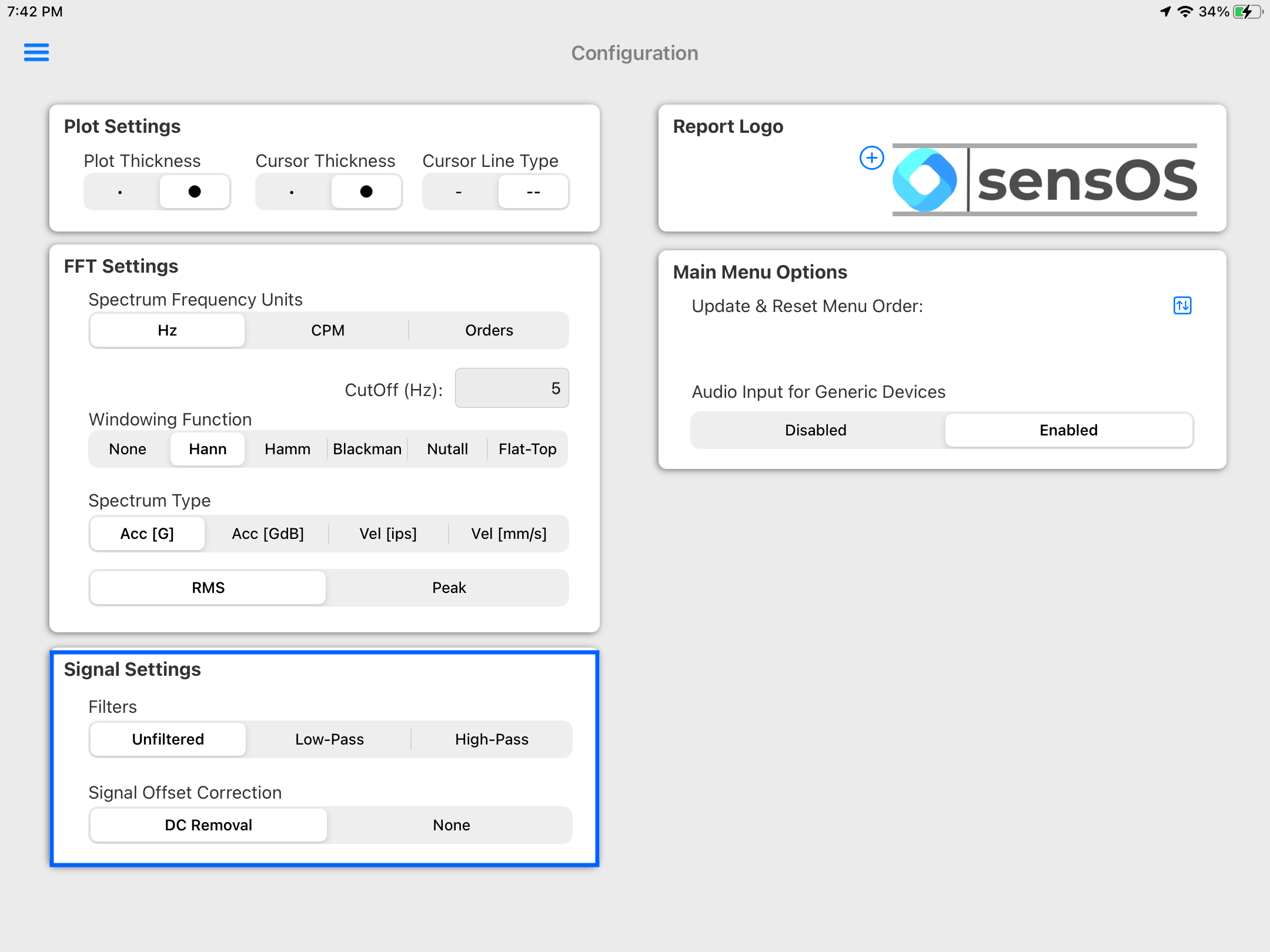
Note: This selection will affect all reading's raw data for all modules

Report
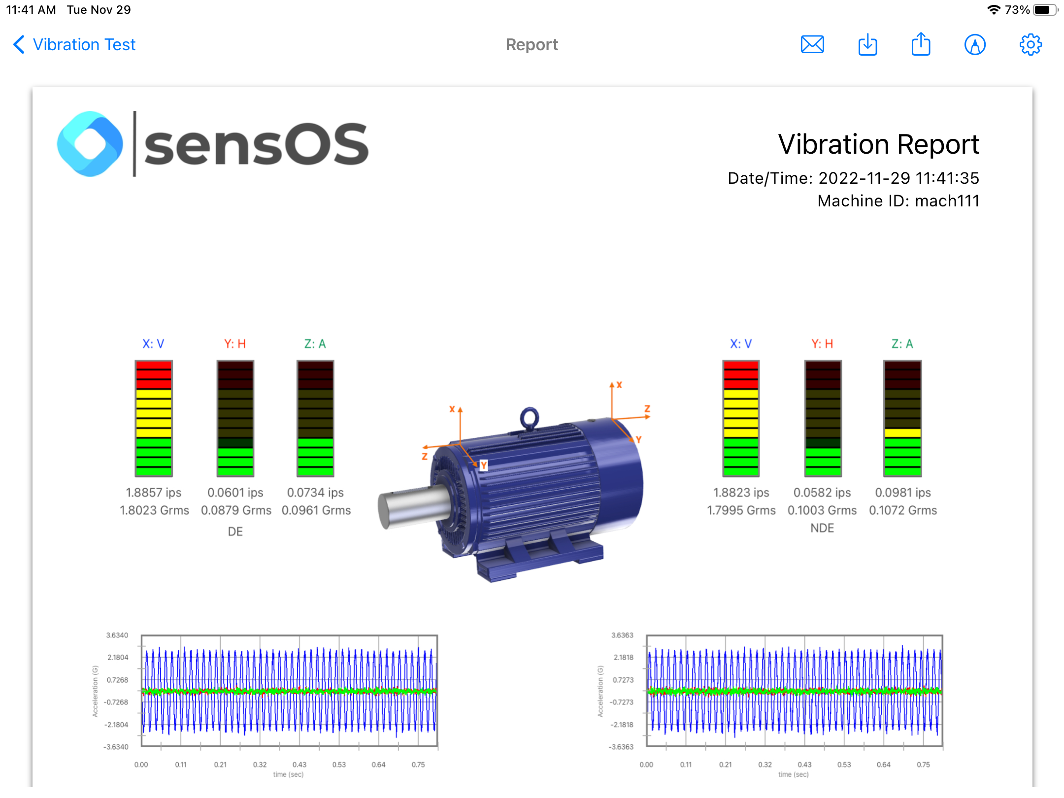
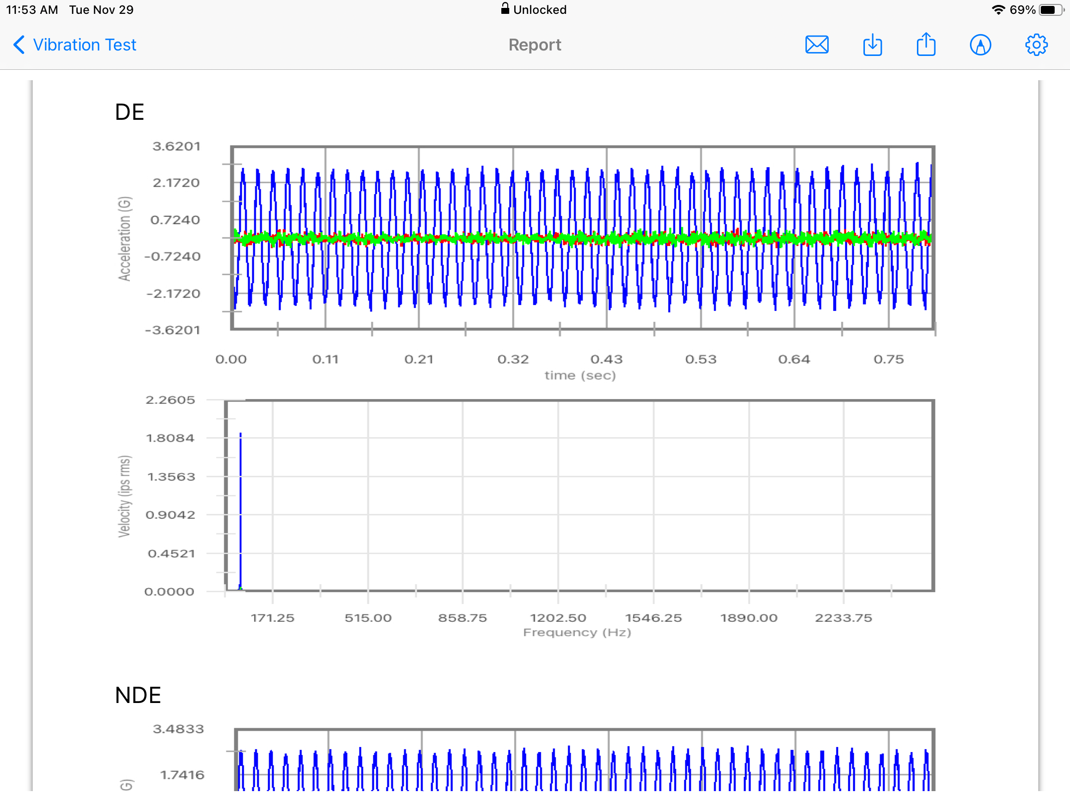
- Clicking on the Report button will open a new view with the pdf report. The report will have the main screen as a frist page, with the asset picture if any, and a second page with the triaxial time-waveform and spectrum for each point.
- The report view contains several options in the top bar menu: 1:Send by Email, 2:Save pdf locally, 3:Upload Report to the Cloud bucket, 4:Markup and 5:Report Configuration
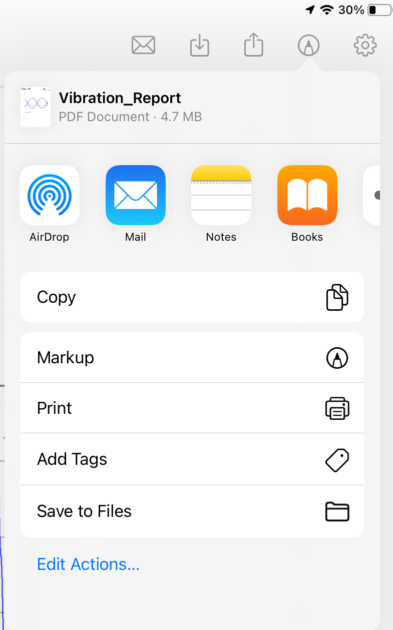
- The markup tool allows the user to copy the report to the clipboard, send it by Airdrop or any other messaging app, email it, print it or saved it to Files. The markup tool will open the standard tool to paint on the pdf report.
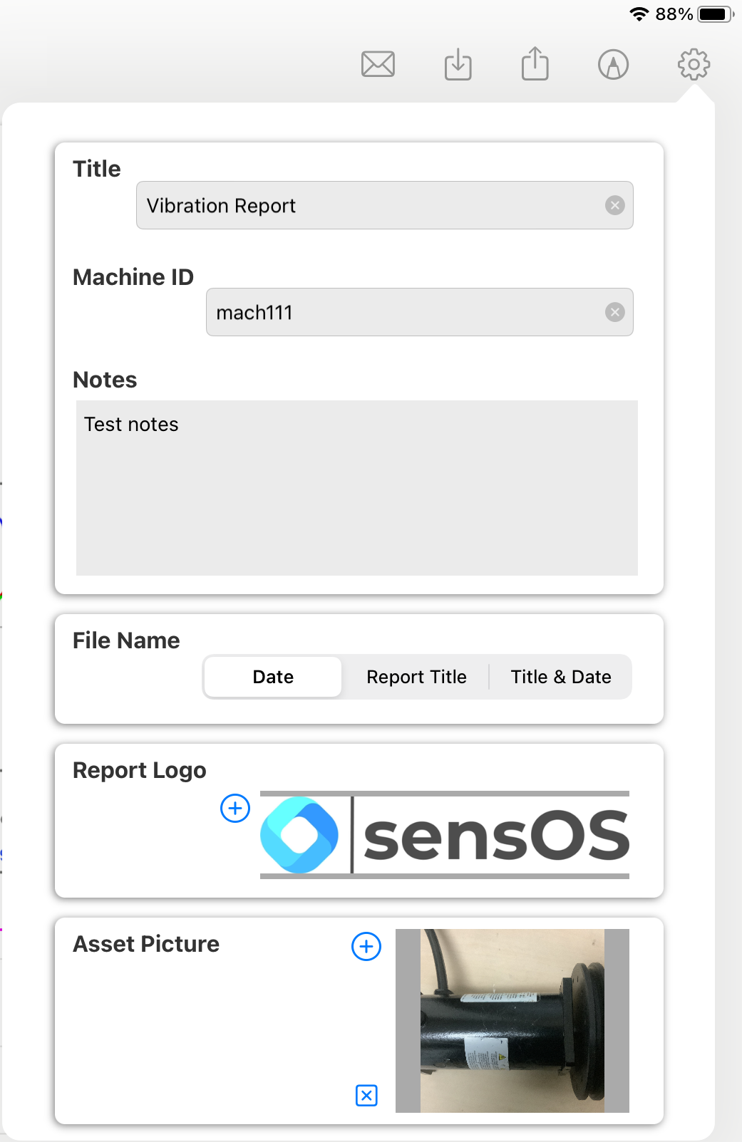
- The Report Configuration pop-up allows the user to enter the Report Title, Machine ID and Notes to be added to the report. Here the user can also select a logo for the report and include a picture of the asset that will be added in a new page in the report. The report file name be default is the actual date and time, but the user can change it to the title name of the report or to both, the title name and date.
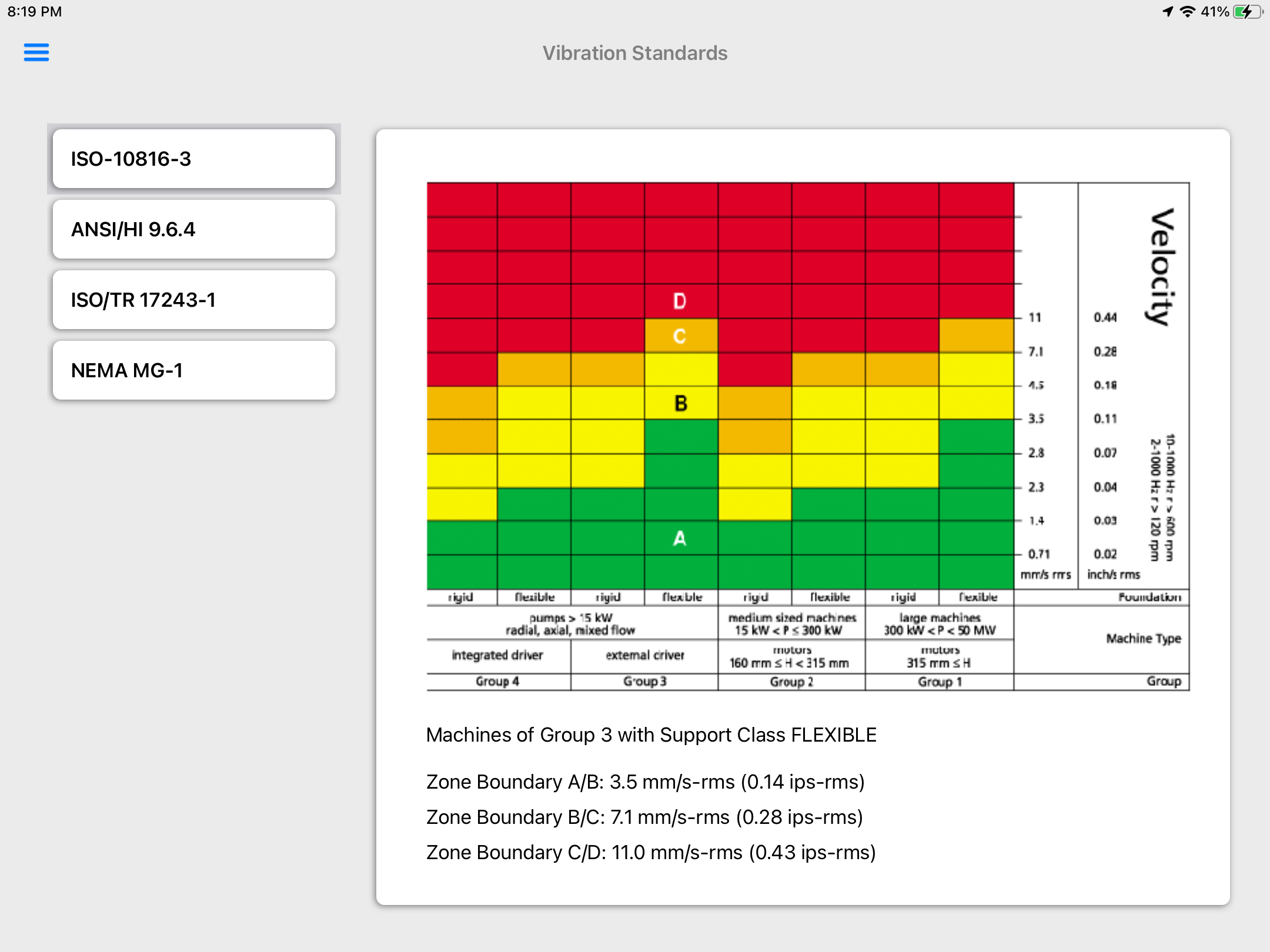
Vibration Standards
- On the main menu click on the top bar left button to open the left drawer, then select the 'Vibration Standards' option.
- On the ISO 10816-3 Standard tap on the selected group to get the vibration threshold values.
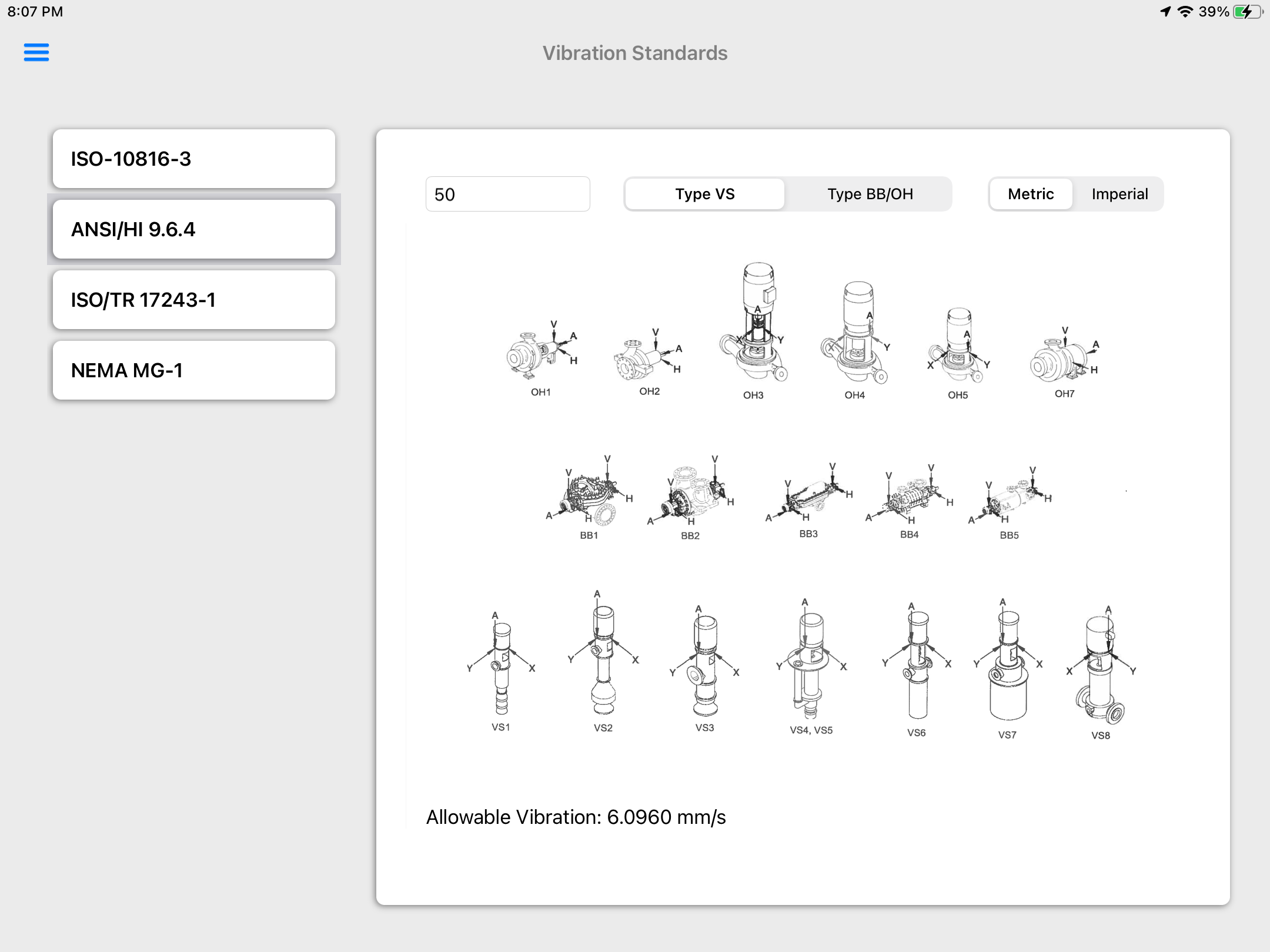
- The Hydraulics Institute ANSI/HI 9.6.4 provides allowable vibration values for hydraulic pumps. Enter the machine Horsepower and pump type, then tap on the desired pump icon to get the allowable vibration value.
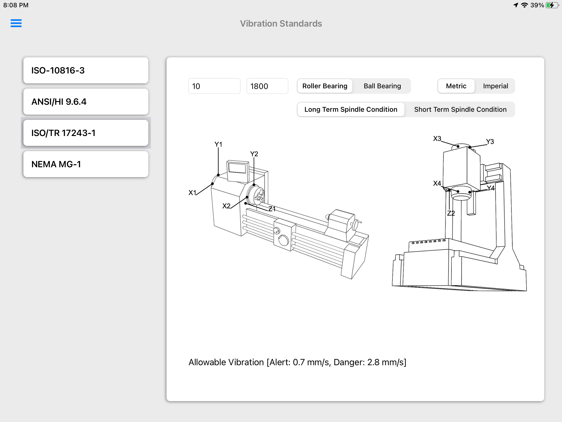
- The ISO/TR 17243-1 provides vibration thresholds for spindles. Enter the machine Power and RPM, select the type of bearing and select the term condition to get the alert and danger thresholds.
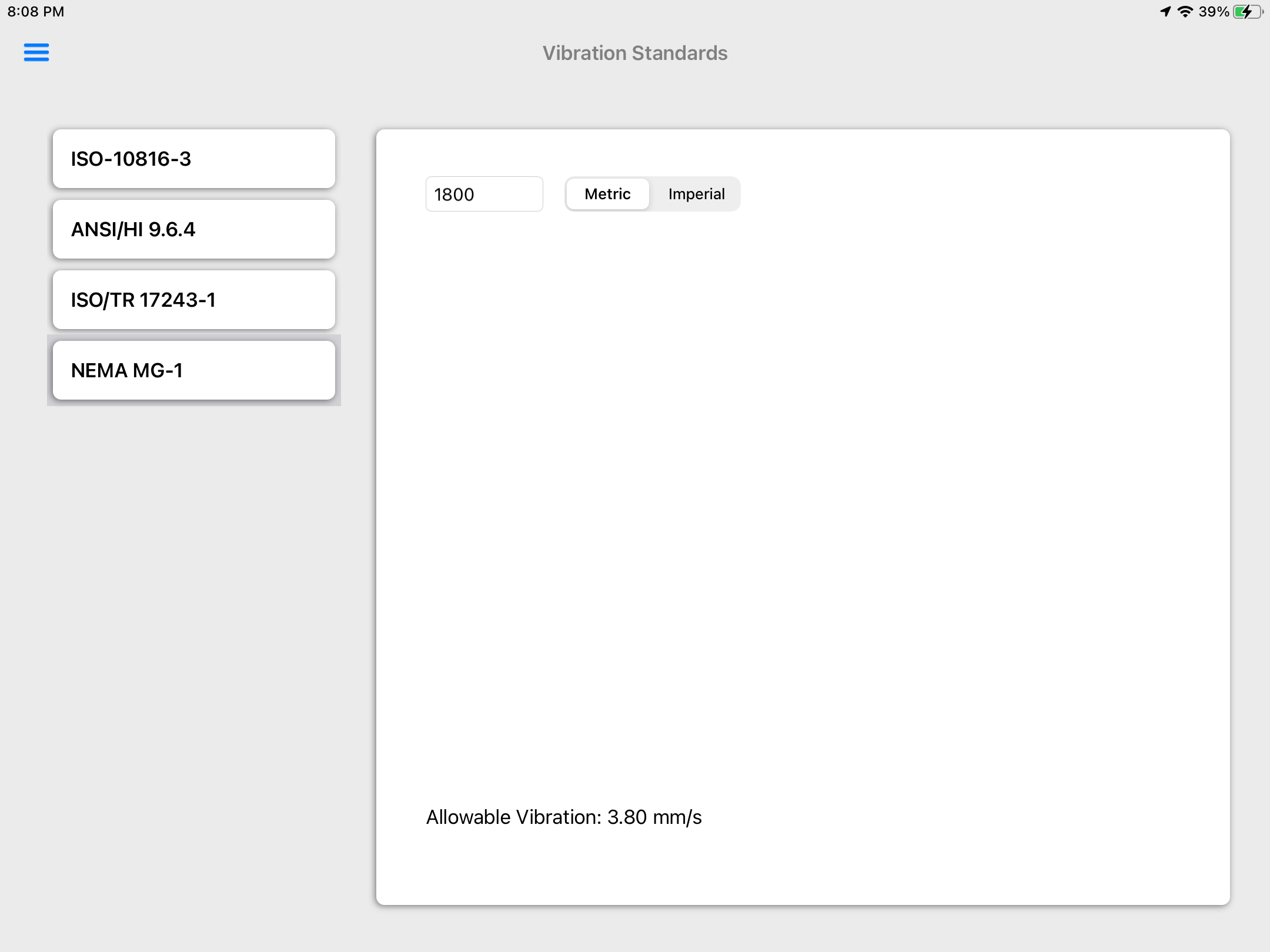
- The NEMA MG-1 provides vibration thresholds for electric motors. Enter the machine RPMto get the allowable vibration value.
Technical References
- ISO 10816-3:1998 Mechanical vibration — Evaluation of machine vibration by measurements on non-rotating parts — Part 3: Industrial machines with nominal power above 15 kW and nominal speeds between 120 r/min and 15 000 r/min when measured in situ
- ANSI/NEMA MG 1-2021 Motors and Generators
- ANSI/HI 9.6.4-2016 Rotodynamic Pumps For Vibration Measurement And Allowable Values
- ISO/TR 17243-1:2014 Machine tool spindles — Evaluation of machine tool spindle vibrations by measurements on spindle housing — Part 1: Spindles with rolling element bearings and integral drives operating at speeds between 600 min-1 and 30 000 min-1
- ISO/TR 17243-2:2017 Machine tool spindles — Evaluation of spindle vibrations by measurements on non-rotating parts — Part 2: Direct-driven spindles and belt-driven spindles with rolling element bearings operating at speeds between 600 r/min and 30 000 r/min
- vibEngine© framework
- vibeFDaD© framework
Changelog
See what's new added, changed, fixed, improved or updated in the latest versions.
Version 1.49 b.126 (21 Nov, 2022)
- Optimized Optimized for iPadOS®16
Version 1.22 b.85 (11 Nov, 2021)
- Added Added compatibility for single-axis readings
Version 1.11 b.70 (31 Mar, 2021)
Initial Release for Triaxial Readings